
1. Measure Before You Adjust
"Feels tight enough" is not a torque reading. Before touching any setting, confirm that what you are measuring is comparable to what the specification describes:
Reading | What it tells you | Where it goes wrong |
Application torque | The torque applied while the cap is being seated — the number that matters for seal integrity | Measured on a removed cap after the fact; always lower than applied value |
Removal / break-loose torque | Force needed to unscrew a capped bottle — the number consumers experience | Rises over hours as the liner relaxes, so it is not interchangeable with application torque |
Clutch setpoint | What the head is told to deliver | Drifts as magnetic powder cakes or friction discs wear; never assume it equals delivered torque |
Station spread | Difference between the highest and lowest station on the same turret | A wide spread points to mechanical wear, not to a wrong setpoint |
Test at least three bottles per station, at the start, middle and end of a run, with the same torque tester and the same operator technique. A single spot check on one station cannot tell you whether the problem is global or local.
2. The Four Zones
Every torque fault belongs to one of four zones. Identifying the zone first prevents the most common waste of time in capping rooms: re-calibrating a capping head that was never the problem.
Symptom pattern | Zone to inspect first |
All stations, all bottles, both directions | Zone 1 (cap/bottle interface) or Zone 4 (recipe) |
One or two stations only, consistent | Zone 2 (head/clutch) |
Specific bottle positions on the turret, drifting with speed | Zone 3 (handling) |
Fine at low speed, fails as line speed rises | Zone 4 (recipe/speed relationship) |
3. Zone 1: Cap & Bottle Interface
This is where most "the machine is broken" complaints actually originate, because a cap that was reformulated or a bottle neck that arrived from a different mould changes the torque result without any machine fault.
- Liner compression set: a softer or thinner liner reaches seal at a lower application torque — the same setpoint now over-tightens and distorts the cap
- Neck finish tolerance: neck diameter at the upper limit needs more torque to reach the same thread engagement; mixed-cavity bottles produce a bimodal torque distribution
- Cap material and temperature: PP caps behave differently in a cold filling hall than in a warm one; caps stored near a heater or in direct sun soften and strip earlier
- Thread start condition: a cap that cross-threads on the first turn never reaches a valid torque reading, it reaches a jam
Practical check: take 20 caps and 20 bottles from the current batch, cap them by hand with a calibrated hand torque tester, and compare against the machine result. If hand-capped bottles also fail, the fault is upstream of the machine.
4. Zone 2: Capping Head & Clutch
Once the interface is cleared, a single-station fault almost always lives here.
- Magnetic clutch calibration: verify the setpoint against a torque tester on that station only; if the delivered value is low at the same dial setting, the magnetic powder has caked or the gap has changed
- Friction disc and spring fatigue: a worn disc delivers torque that falls off during a long run rather than immediately — the symptom is "good at startup, loose after two hours"
- Spindle and bearing play: vertical float that sticks prevents the head from following the cap down, so the cap is spun before it is fully seated
- Head-to-bottle centerline: an offset head presses on one side of the cap, producing a torque reading that looks acceptable while the cap is visibly cocked
- Gripper/spinning roller wear: uneven roller contact scores the cap skirt and reduces effective grip, which reads as low torque on that station
A quick isolation test: swap the suspect head with a known-good head from an adjacent station. If the fault follows the head, the head is the cause; if it stays at the position, the cause is in the turret, the clamp or the bottle path.
5. Zone 3: Bottle Handling
A bottle that rotates while the head is turning absorbs torque that never reaches the cap. This zone produces the most misleading readings, because the head is doing exactly what it was told.
- Clamp grip force: fatigued springs or product residue in the jaws let the bottle spin; the cap looks loose but the head delivered full torque
- Starwheel centering: worn neck pockets shift the bottle off the head axis, creating side load and inconsistent engagement
- Bottle shape and fill level: lightweight or tall bottles flex under clamp pressure; a bottle that deforms releases grip mid-cycle
- Conveyor backpressure: excessive accumulation pressure pushes bottles against the starwheel, changing the effective clamping geometry at the capping station
- Lubrication carry-over: conveyor lubricant on the bottle body reduces the friction the clamp depends on — a frequent cause after a change of lubricant supplier
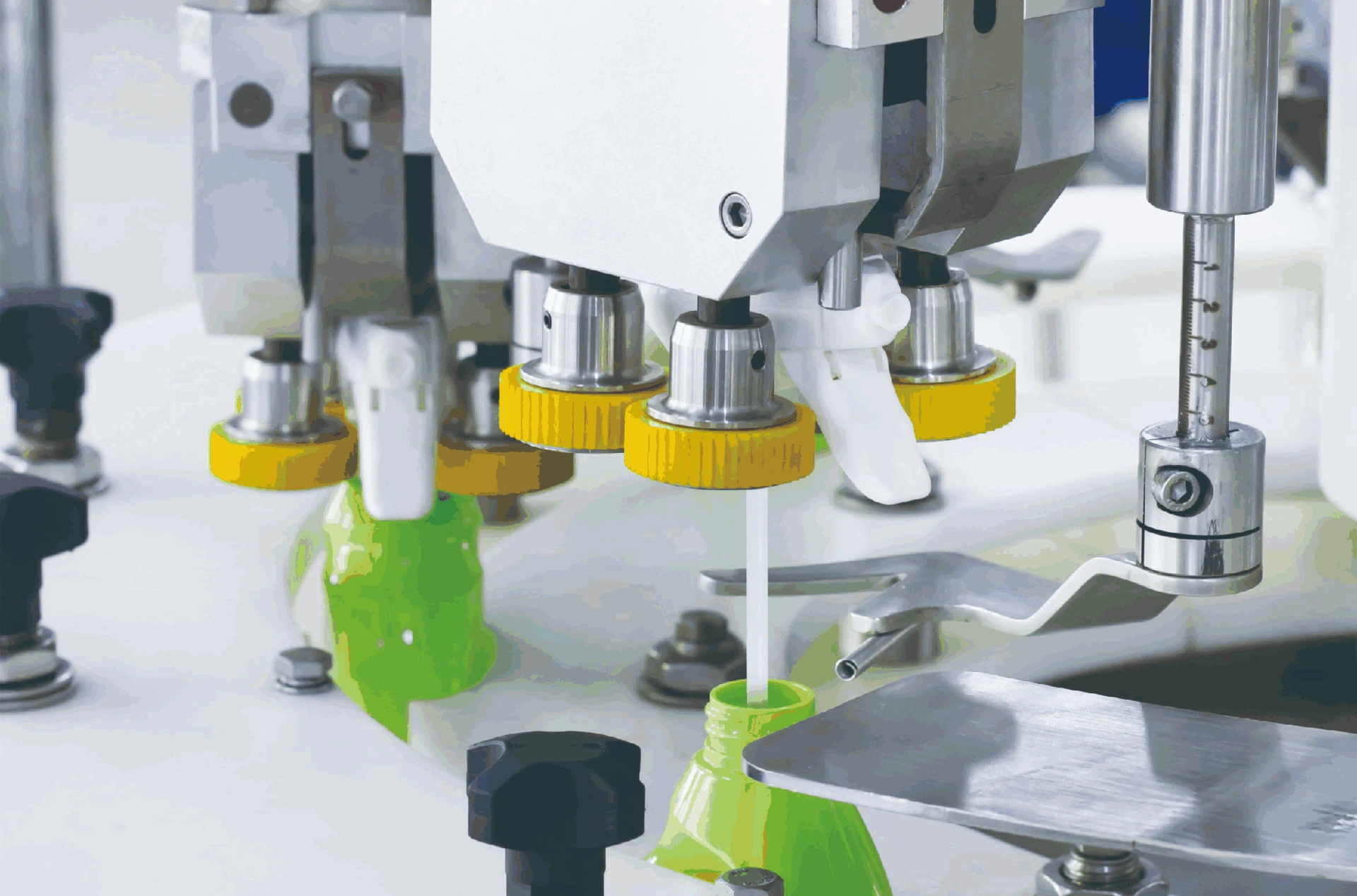
6. Zone 4: Recipe & Speed
Torque is not constant across the speed range. If a line passes at 120 bottles per minute and fails at 200, the recipe is the place to look, not the hardware.
Variable | Effect on delivered torque | What to check |
Turret speed | Shorter contact time per head reduces effective torque | Whether the recipe's torque compensation is enabled and correctly mapped |
Head dwell / cam profile | Less cam lift time means the cap is not fully seated before spinning | Cam timing against the manual's setting for the current cap height |
Cap height change (changeover) | A different cap height changes the presser's working stroke | Head height re-set and re-verified with a first-piece sample |
Bottle height variation | Mixed bottle heights change head travel | Whether bottle height is controlled upstream within the manual's tolerance |
Ambient temperature | Changes cap and liner stiffness | Seasonal recipe adjustment, documented rather than ad hoc |
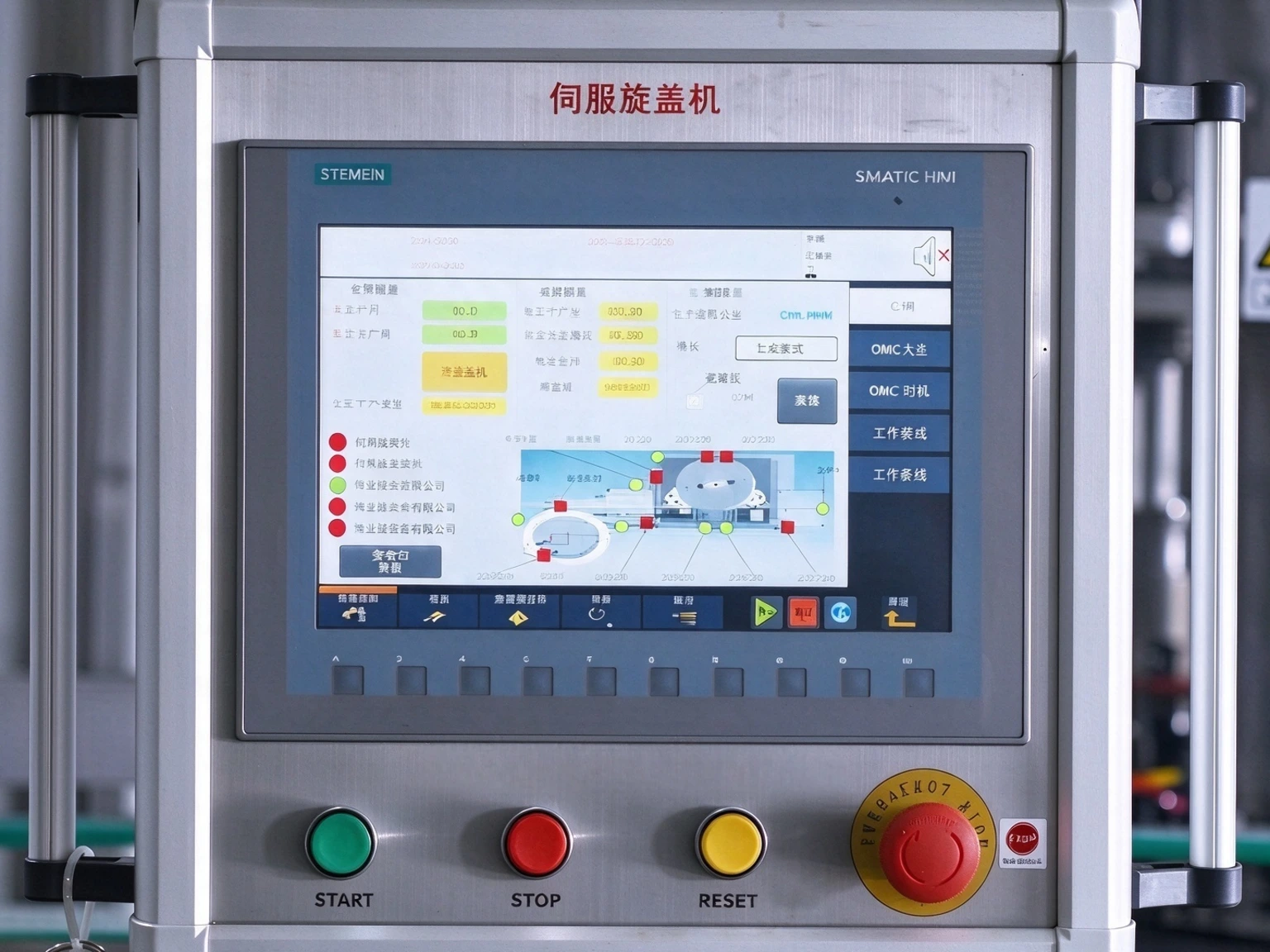
7. Diagnostic Matrix
Symptom | Station pattern | Most likely cause | First test |
Caps loose, all stations | Global | Liner change, neck tolerance, or torque setpoint too low | Hand-cap 20 samples to isolate machine vs. components |
Caps loose, one station | Local | Clutch calibration, worn friction disc, roller grip | Swap head with adjacent station; retest |
Caps over-tightened and distorted | Global or speed-dependent | Setpoint too high for the new liner, or missing speed compensation | Lower setpoint in 0.2 N·m steps and re-check seal |
Threads stripped or cross-threaded | Random, worsens at speed | Cap not seated before spinning; head float sticking; cap skewed in chute | Check cam timing and head vertical freedom |
Torque drifts during a run | Progressive | Friction disc or spring fatigue, thermal growth, powder caking | Log torque every 30 minutes against elapsed run time |
Torque varies bottle to bottle | Alternating positions | Bottle rotation in clamps, starwheel off-center, backpressure | Watch the clamp at the capping station at low speed |
Cap cocked but torque reads OK | Local | Head-to-bottle centerline offset, worn presser | Check presser contact pattern with carbon paper |
8. Verifying a Fix
An adjustment is not a fix until it holds across the speed range and across a shift change.
1.First piece: three bottles per station, torque recorded by station number, not averaged
2.Speed sweep: sample at minimum, nominal and maximum line speed — the failure often returns only at the top end
3.Thirty-minute recheck: friction-related faults reappear within half an hour if the disc is the real cause
4.Shift handover note: record the setpoint change, the reason and the batch of caps in use, so the next shift does not "correct" it back
5.Seal verification: torque is a proxy, not the goal — confirm seal integrity on the actual product before releasing the batch
Relevant product reference:
If torque consistency cannot be held across the speed range on an existing machine, the limitation is often mechanical rather than procedural. Review the High-Speed Automatic Screw Capping Machine for servo-driven head control, or the Rotary Capping Machine Category for the wider range of turret configurations.
Next step:
For machine-specific torque recipes, head calibration procedures and changeover sequencing, start with the Automatic Capping Machine Setup Guide. For the wear-part side of the same problem — heads, clamps, discs and their replacement triggers — see the companion guide Rotary Capping Machine Maintenance Checklist.